Mechanical Gyroscope


Mechanical Gyroscope
Published 2018-03-23T12:10:55+00:00
My intention in designing this gyroscope was to inspire innovation. I study mechanical engineering and plan to pursue a career as a mechanical design engineer. This creation incorporates four components used mechanical assemblies.
- Gyroscopic Motion
- Gear
- Roller Bearing
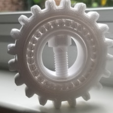
- Bolt
I chose these specific components because they are used to achieve a variety of purposes. Gyroscopic motion is used in navigational equipment, gears are used in power transmission and speed adjustment, roller bearings are used to reduce friction in rotational motion, and bolts are used to fasten everything secure in place. Together, these components embody features of many mechanical designs.
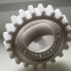
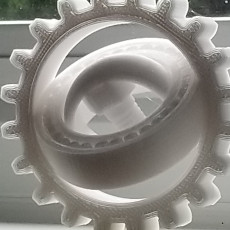
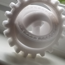
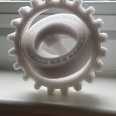
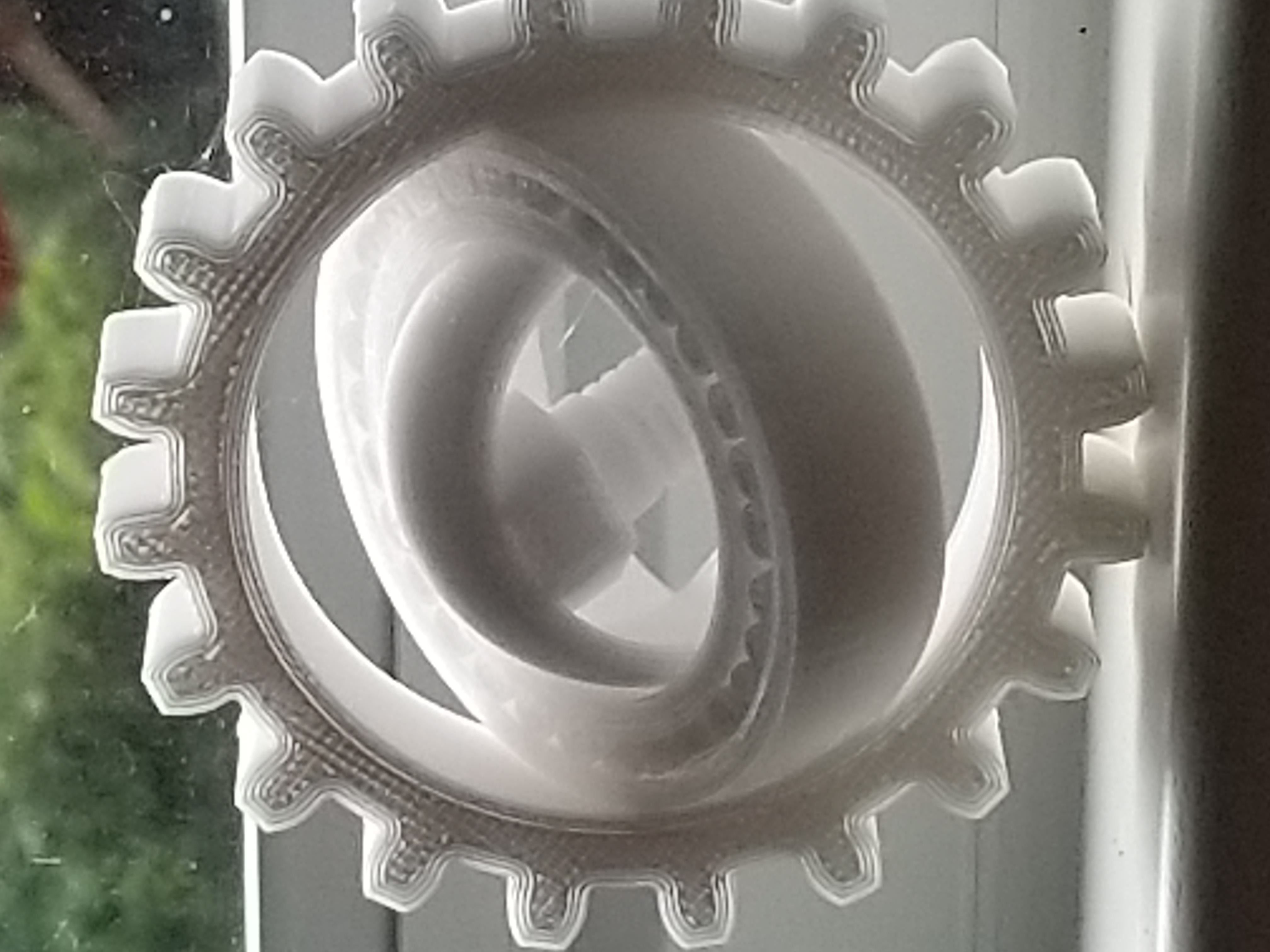
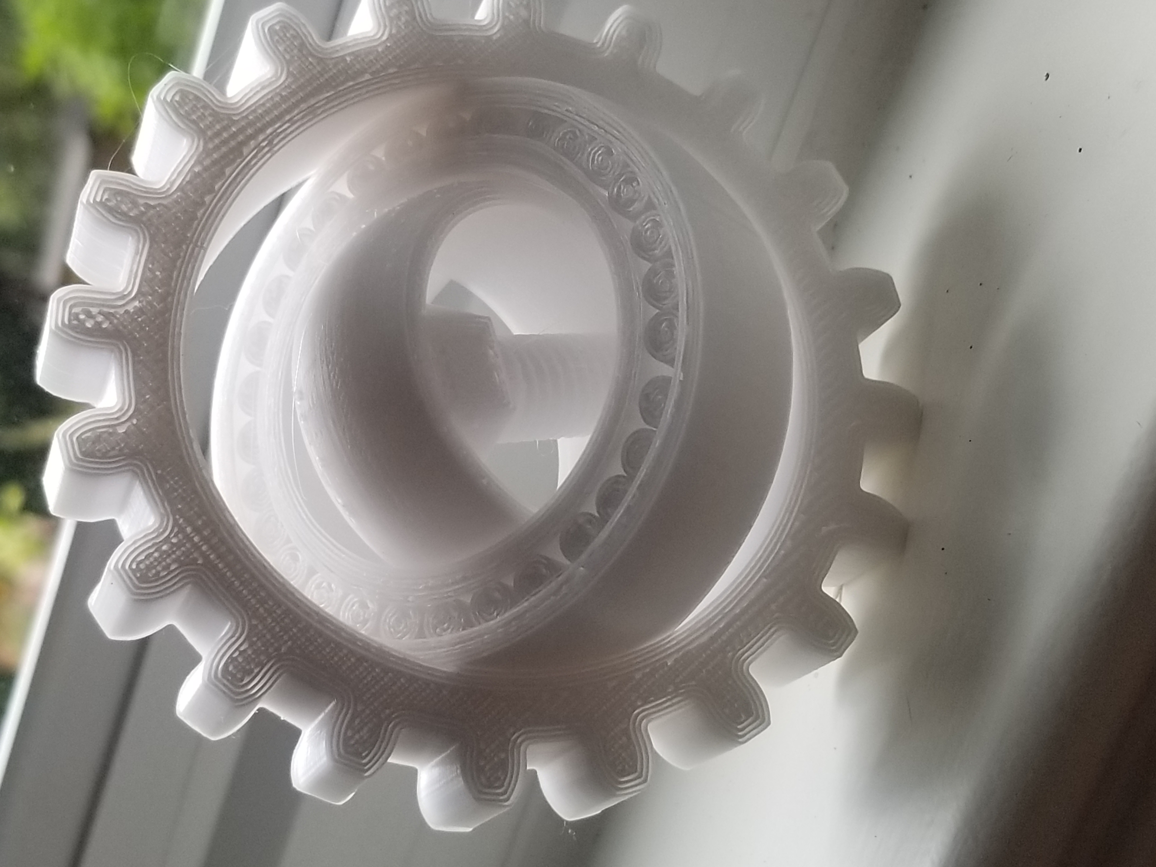
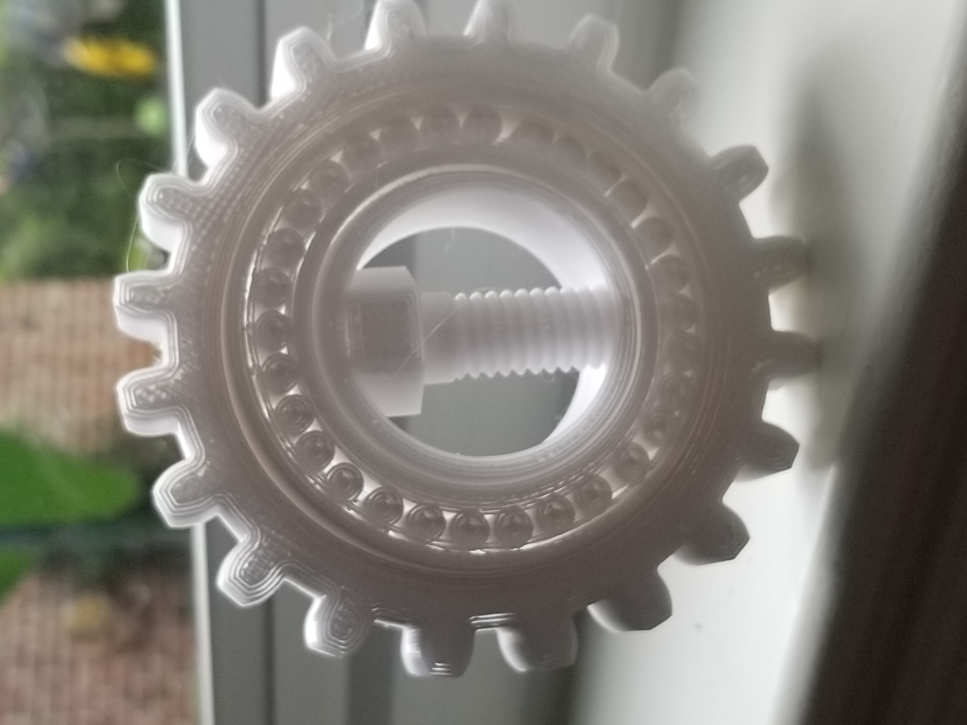
The gyroscope has three main parts: the outer gear, roller bearing, and inner ring. The gyroscope has a full range of motion. All three rings spin and rotate independently of each other. The roller bearing within the middle ring provides additional mobility.
Dimensions:
- 94.0 mm overall diameter
- 18.4 mm thickness
This model was designed in Fusion 360.
Enjoy and happy printing! :)


The model can be printed all at once, or in three individual parts. Support material must be used (touching the build plate only) for printing the roller bearing and inner ring. This provides a foundation for the individual rollers and improves the thread quality on the bolt. A few minutes of post-processing support removal and spinning of the bearing allows it to "loosen-up" and spin freely. This part was printed with 3 perimeters and 30% infill, but would likely work just fine with less.
| Date published | 23/03/2018 |
| Dimensioni | 94.0mm x 18.4mm |
| Tecnologia | FDM |
| Complessità | Easy |


I printed these in white PLA filament on my Ender 3. I wish I'd have used my glow in the dark filament, but this is a really cool model. It works great!